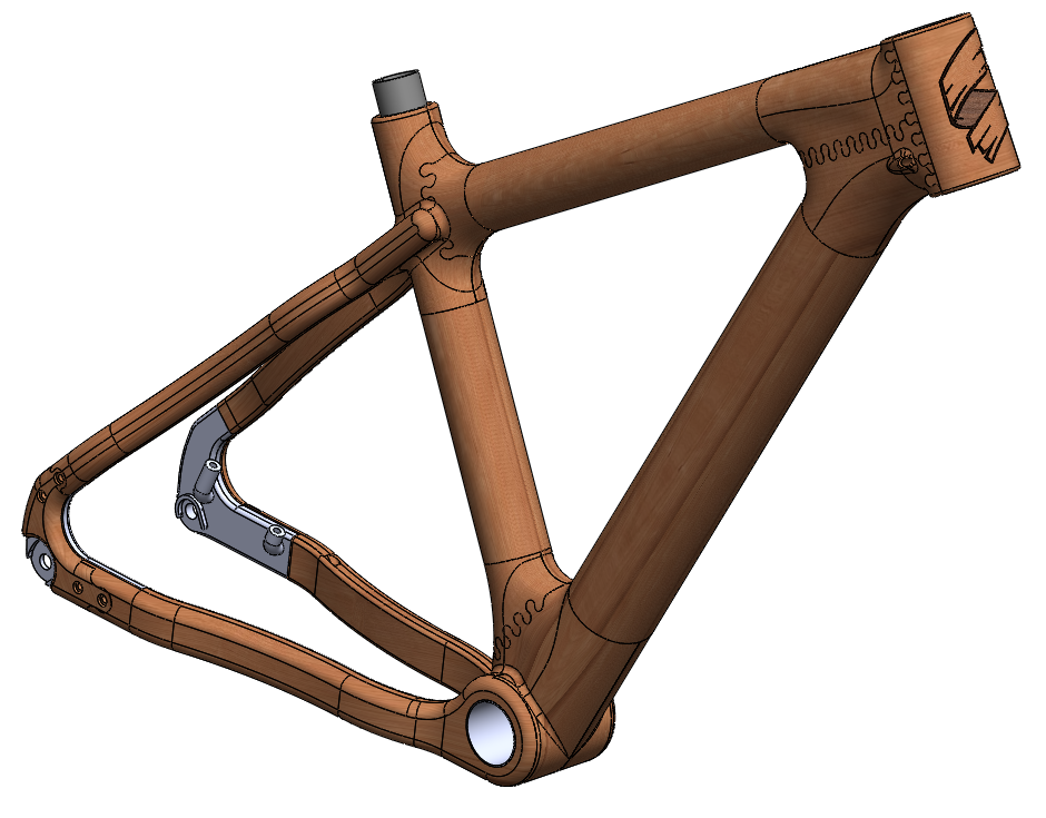
After the first bike, I had the bug, and I knew I could improve. I wanted to make the tubes thinner wall to save weight and I wanted to dive deeper into the wood selection process, especially in property comparison to, say, aluminum bike tubes.
I also had a totally new construction method in mind, and to top it all off, I wanted to make a mountain bike this time. So, just a few changes from the first model.
First I dove into the wood selection process. Using material properties I got from The Wood Database (https://www.wood-database.com/) I wrote a MatLab script that would calculate section properties of wood tubes and compare them to an existing mountainbike tube set available for purchase from Nova Cycles (https://www.cycle-frames.com/bicycle-frame-tubing/). See the post titled: “Wood as an Engineering Material” for some more info about this.
The script gave me a list of useable woods and rated their suitability. With this info in hand, I turned to the next new aspect: the construction method.
For this new bike I want to build a lugged frame instead of the half lap jointed frame of the Mk 1. This necessitates making wood tubes. There are a couple ways of doing this, but the most promising method to me for making thin walled wood tubes was to laminate them from veneers, somewhat similar to how composite tubes are made. Wood is, after all, nature’s carbon fiber.

Originally I intended to layup the tubes with a schedule similar to a carbon fiber tube in that I would have some layers running axially and some biased. The plan was to layup with the following schedule: [0°/0°/-45°/+45°/0°/0°] starting from the inside of the tube working outwards. The biased layers were intended to help increase torsional rigidity and resist crushing. I say I originally intended to do this because that isn’t how things worked out. Turns out that wrapping a thin veneer tightly in a spiral around a tube without cracking it is pretty difficult. Doing so while epoxy is making everything slippery and generally uncooperative is even more of a headache.
So I decided to go with a purely axial orientation of the grain and built my tubes without any biased layers involved. I’m working on a more in-depth post about making these tubes, so keep an eye out for that.
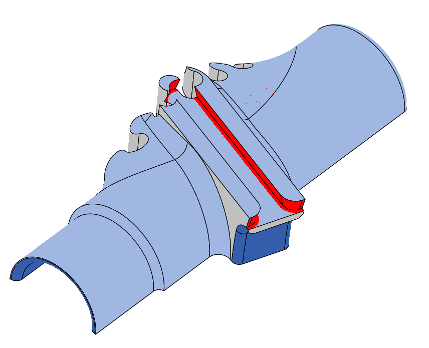
With the tubes sorted out, I turned my attention to the lugs. Each of these is composed of several pieces cut and joined together with Isoloc joints.
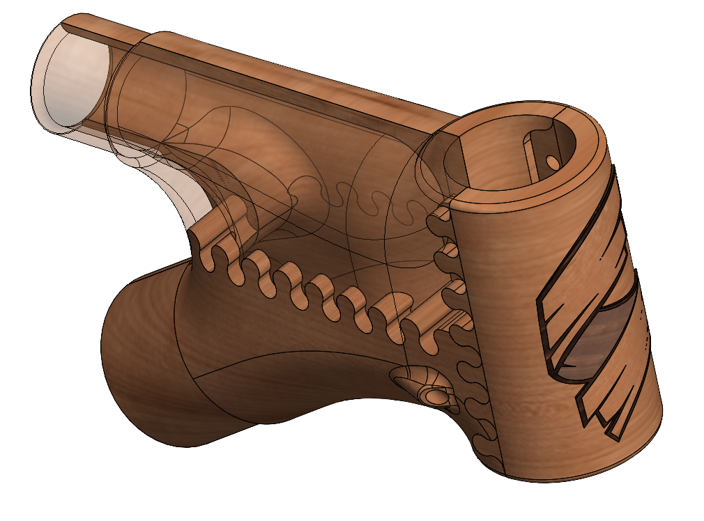
The lugs are made in a similar fashion to the first bike in that I am making them in two halves, machining out the inside, then putting those halves together to form a hollow piece. The joinery is different, and I am using a CNC to do all the cutting this time around, but the concept is basically the same.
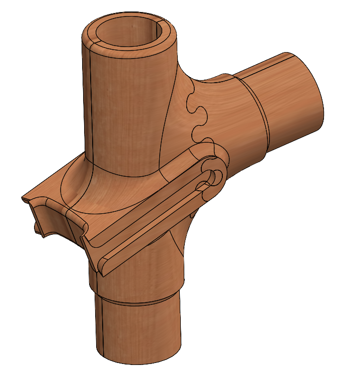
Because I am making these lugs using a 3 axis mill, it is important to design them in such a way that I can get to all the surfaces in as few setups as possible. I made use of Solidworks undercut analysis tools to refine some of the surfaces of my part to ensure I had no occluded areas.